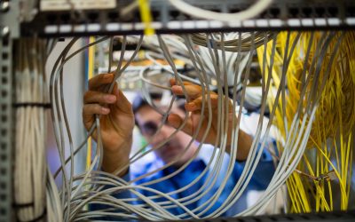
Inspecting Twisted Pair Cabling Systems

Tags: cabling | installation | training | twisted pair
This article provides the reader with some guidelines and practical experience to help inspect copper cabling installations.
The guidance provided should help achieve installed cabling system that meet or exceed TIA, ISO and EN cabling standard requirements.
All pathways, spaces, cables, connection hardware, support structures, and any other relevant requirements should be clearly documented by the cabling designer and approved by the customer prior to installation. Any unexpected circumstances, some of which may be identified during installation, should be immediately verified and/or resolved with the designer.
Cable Installation
The following issues must be addressed during cable installation.
Splices, taps, or repairs are should not be allowed. Damaged or broken cables must be replaced or decommissioned.
When installing horizontal cables in an open environment, route the cables a minimum of 5 inches (120 mm) away from fluorescent lighting fixtures.
For communications cables, the separation distance needed from electrical branch circuits should be considered and guidance taken from the cabling standards or manufacturer.
Cable Fill
Cable trays, conduit, and raceways have cable fill limits that must be followed to avoid overpacking the cables. The system design should identify specific limits.
Cable Stress
The installation requires the elimination of cable stresses due to tension, cinching, etc.
Tie wraps must be hand tightened without tools (tight enough to snugly hold cables together). Stress on the cables may cause pair de-twisting. Velcro bands are often used as alternative. Spacing between tie wraps should be at least 1 m.
Hanging supports such as J-hooks or cable rings must be within 1.5 m (5 ft. ) centers.
Cable spans between such hanging supports must exhibit a visible sag as an indication of acceptable cable tension.
Heavy pulling tensions should be relieved after the pull.
When pulling in conduit or raceways, minimize pulling tensions by smooth uniform pulling and continuous management of cable feed.
Be aware of the cables maximum pulling tension. Manual pulling is preferred.
Document all installation activities and results.
Cable Handling
Although there is no strict limit on the number of bends in a cable, installers should avoid unnecessary bends. Most manufacturers guidelines (and cabling standards) have a requirement for minimum bending radius of no less than 4 times the cable diameter.
Avoid the following situations:
- Folds that exceed 90°.
- Tight twisting of cable. This is sometimes caused by overtight tie wraps close to cable bends, or by pulling a cable that has looped on itself.
- Torn jacket, cutting, or wear-through due to abrasion or sharp edges.
- Scoring the jacket should not cut into the copper conductors.
- Installers should strip back only enough cable jacket to properly terminate cable pairs.
Bending pairs without tension has a tendency to spread conductors apart and distort pair twists. To avoid this, unjacketed pairs must be tightly pulled around all bends. This forces the copper conductors to set and remain in place. It should be tight enough to maintain undistorted pairs but not so tight as to damage insulation or conductors.
Panel and Outlet Termination
For details on the termination techniques and therefore the recommended installation procedures for different panels and outlets, ensure you refer to the relevant design and installation guidelines of the manufacturer.
Inspection
Conformance to the installation practices covered are straightforward to verify when completed. The following points should be examined:
- Is the design documentation complete?
- Have all terminated cables been tested for continuity and shorts?
- Have the length measurements (TDR) been completed and recorded?
- Is the cable type suitable for its pathway?
- Have the pathway manufacturer’s guidelines been followed?
- Have the installers avoided excessive cable bending?
- Have potential EMI sources been considered?
- Is Cable Fill correct?
- Are hanging supports within 1.5 m (5 ft)?
- Does hanging cable exhibit some sag?
- Are telecommunications closet termination’s compatible with applications equipment?
- Have Patch Panel instructions been followed?
-
- Cable dressing first
- Cable jackets remain up to the IDC Connecting Block
- Pair termination’s tight and undistorted
- Twists maintained up to the IDC Connecting Block
- Is the cable jacket maintained right up to the Telecommunication outlet?
- If a short length of cable is unjacketed, have supplementary guidelines been followed?
- Maximum unjacketed length 4 cm. (1.6 inch)
- Do not let Open Loops form at bends
- Do not let the pairs be pushed under force as the outlet is mounted
- Do not twist pairs into each other
This is not an exhaustive list, so if you are interested in learning more, take a look at the Network Project Planning and Safety or Network Test and Inspection courses.

Written by James Donovan
You might also enjoy
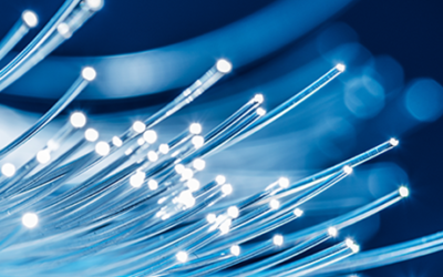
FO Connector Contamination – A Constant Threat
Fiber optic communication most commonly works in duplex or multifiber transmission by transmitting light to a receiver in one direction on a fiber and receiving transmitted light back to a second receiver on the second fiber. Most engineers can understand that and...
Why Inspect and Clean Fiber Optic Connectors?
Inspecting and cleaning of fiber optic connectors during installation and when making any patching, is essential. Any contamination on a patch cord connector will be transferred through the coupler to the connector it is mated to. Even when testing fibers with a test...

Cleaning MPOs
MPO connectors should always be inspected with a scope before they are used, be that on a patch cord or a bulkhead. If they need to be cleaned, one-click cleaners are keyed to ensure the tip only fits one way onto the connectors and is able to clean both male and...